Hi,
I have been designing an EEG device, and I am currently looking into the design of the analog filter stage before being fed into the ADC. I am only interested in high delta to alpha band signals, so I was intending to design a simple differential mode bandpass filter (my design is in bipolar montage) consisting of a ESD detection/prevention stage, a high-pass stage with cutoff frequency around 30 Hz, and a low-pass stage with cutoff frequency around 1Hz. I’ve been advised not to use common-mode shunt capacitors to reduce CMRR since common mode noise is-hopefully-not going to be a huge issue.
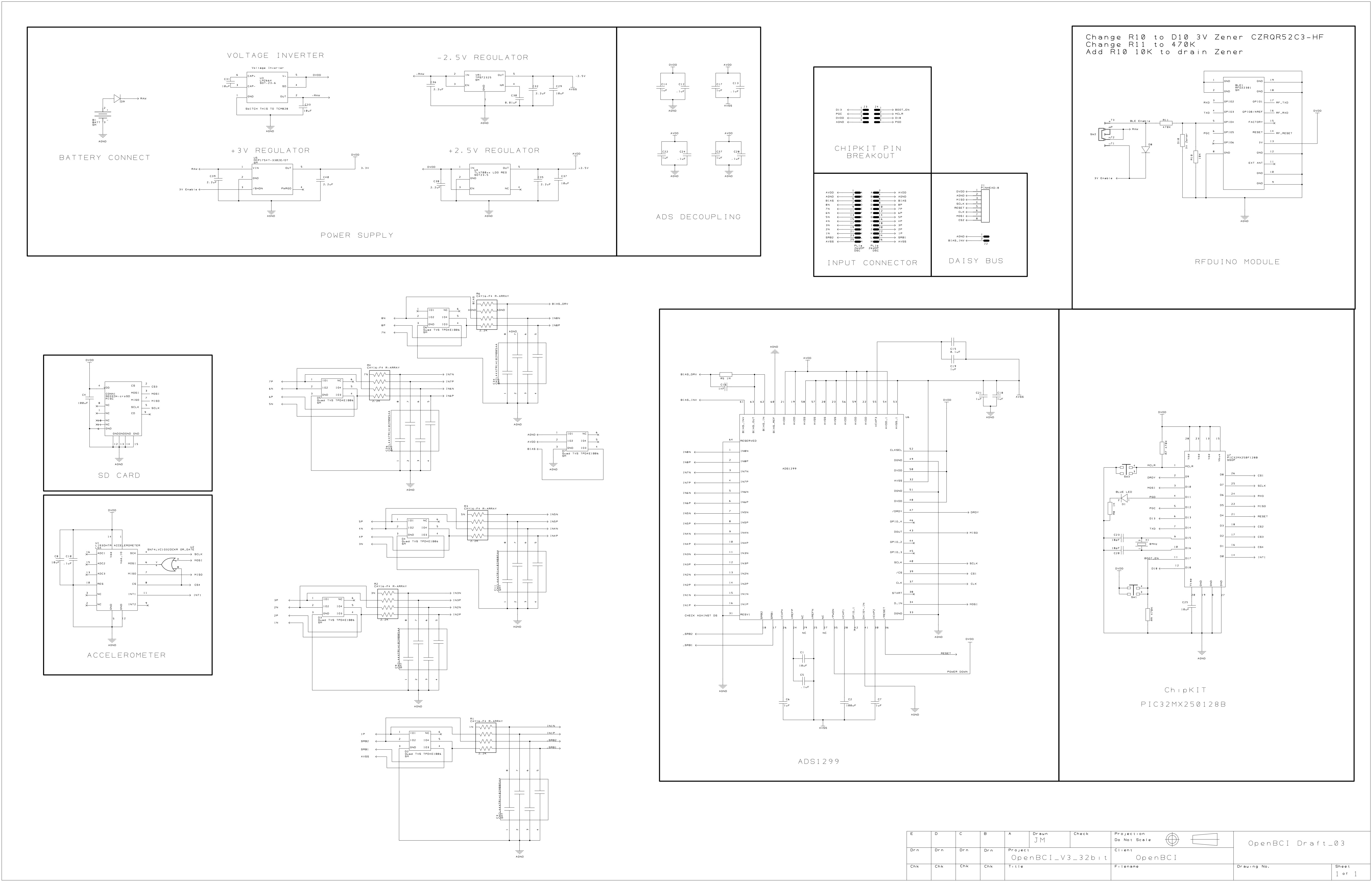
To sanity check, I referenced the openBCI Cyton board schematic and I was a little perplexed by what I found. As far as i can tell, the Cyton board is in referential montage and uses only an ESD stage and a common-mode low-pass filter. But that filter seems to have a ridiculously high cutoff frequency–if the resistors are 2.2kΩ and the capacitors are 1000pF, then the cutoff frequency must be f = 1/(2piR*C) = 72 kHz. This seems absurd. Am I missing something?
As a side note, any advice for my filter stage design would be very appreciated. Thanks!
